Next: AC Miniature Circuit Breaker Market Analysis in India(2024-2033)

1. Standard Graphical Symbols for Miniature Circuit Breakers
2. Interpreting MCB Symbols: Poles, Trip Curves, and Applications
3. Advanced MCB Symbol Variations
4. Best Practices for Using MCB Symbols in Electrical Documentation
Modern electrical systems rely on precision, safety, and clarity—qualities embodied by Miniature Circuit Breakers (MCBs). These devices are not just switches; they are guardians against overloading and short circuits, ensuring systems operate within safe limits. Central to their integration into electrical designs are MCB symbols, standardized graphical representations that enable engineers, electricians, and procurement professionals to communicate complex ideas succinctly. This article explores the anatomy of these symbols, their variations, and their pivotal role in safeguarding electrical systems.

Image source: electricaltechnology
Miniature circuit breakers protect circuits from overcurrents, such as short circuits and overloads. When the current exceeds a certain level, it automatically interrupts the flow of current, preventing circuit damage and potential fire hazards. Compared to traditional circuit breakers, miniature circuit breakers are smaller in size, making them ideal for use in tight spaces.
Learn More: MCBs Guide
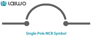
1 Pole MCB Symbol
A rectangle with a horizontal break, representing the interruption point
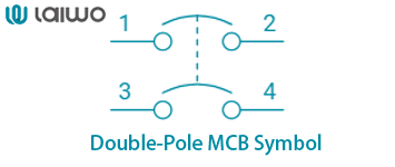
2 Pole MCB Symbol
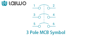
3 Pole MCB Symbol
The RCCB(full form in electrical: Residual Current Circuit Breaker), also commonly referred to as a circuit breaker, is an electrical safety device designed with the primary purpose of immediately interrupting the electricity supply upon detecting any leakage of current that could potentially lead to an electric shock.
Learn More: RCCB Guide
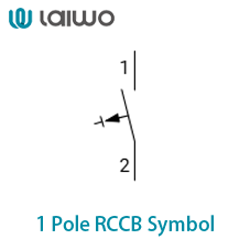
1 Pole RCCB Symbol
a rectangle with a test button symbol inside.
2 Pole RCCB Symbol
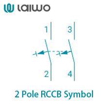
3 Pole RCCB Symbol
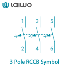
Learn More: Circuit Breakers Symbols
RCBO(full form in electrical: Residual Current Breaker with Overcurrent) is a sophisticated electrical safety device that integrates the functionalities of both an RCCB and an MCB into a single compact unit.
Learn More: RCBO Guide
Electrical schematics are blueprints of safety. At their heart lie MCB symbols, standardized by organizations like the International Electrotechnical Commission (IEC) and the American National Standards Institute (ANSI). These symbols eliminate ambiguity, ensuring global consistency.
Single-Pole MCB Symbol: A rectangle with a horizontal break, representing the interruption point
Multi-Pole MCBs: Linked single-pole symbols. For example, a 2 pole MCB symbol combines two rectangles with breaks, while a 3 phase MCB symbol uses three.
Advanced Features: Symbols with an “x” denote full fault interruption capability; a horizontal dash indicates an isolator.
Base Symbol: A square with horizontal lines or a rectangle with a diagonal slash.
Multi-Pole Representation: Dashed lines link single-pole symbols, emphasizing mechanical linkage.
Annotations: Labels like “C20” (Type C, 20A) clarify tripping characteristics and ratings.
These standards highlight a key divergence: IEC prioritizes granular symbol variations, while ANSI leans on annotations. For B2B buyers, this distinction matters when sourcing components for international projects.
| Poles | Applications |
| 1 Pole MCB Symbol | Safeguards single-phase circuits |
| 2 Pole MCB Symbol | Protects split-phase systems |
| 3 Pole MCB Symbol | For three-phase systems in factories or high-power setups. |
| 4 Pole MCB Symbol | Used in three-phase systems with a neutral line |
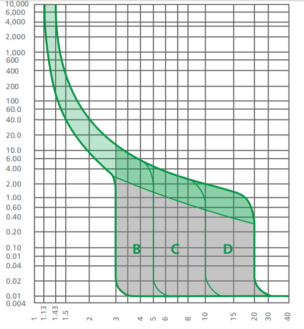
| MCB Type | Trip Curve | Sensitivity | Common Applications | Best For |
|---|---|---|---|---|
| Type B | Trip at 3-5× rated current | High | Residential lighting, sockets | Homes, offices |
| Type C | Trip at 5-10× rated current | Moderate | Motors, HVAC systems | Commercial buildings, industrial gear |
| Type D | Trip at 10-20× rated current | Low | Heavy machinery, transformers | Factories, welding equipment |
While standard symbols dominate, nuances exist:
Thermal vs. Magnetic Tripping: IEC differentiates symbols for thermal (HCB11TH) and magnetic (HCB11Q9) mechanisms.
Differential Protection: Symbols with a superimposed “Δ” indicate ground fault protection.
Historical Variations: Older diagrams may use a simple rectangle with a diagonal line, lacking modern specificity.
For industries like semiconductor manufacturing or healthcare, where high sensitivity (Type Z MCBs) is critical, symbols with specialized annotations ensure compliance with safety protocols.
Consistency is King: Stick to one standard (IEC or ANSI) per project to prevent confusion.
Label Relentlessly: Include current ratings, trip curves, and breaking capacity adjacent to symbols.
Leverage Software Tools: Use CAD libraries for accurate MCB diagram symbols in AutoCAD or Revit.
Contextual Clarity: In single-line diagrams, pair symbols with legends explaining abbreviations like “CB1” (Circuit Breaker 1).
Procurement professionals should collaborate with engineers to ensure schematics align with vendor specifications, especially for high-voltage or custom applications.
As electrical systems evolve, so do their symbols. Smart MCBs with IoT capabilities are emerging, featuring embedded sensors and communication modules. Future schematics might integrate dynamic symbols that update in real-time, reflecting live data on overload conditions or wear levels. For B2B buyers, this shift underscores the need to invest in components compatible with digital twin technologies and Building Information Modeling (BIM).
INQUIRY NOW